The Pneumatic Despatch, by S. J. Mackie
This article describing the London Pneumatic Mail Rail is written in the year 1864 by Samuel Joseph Mackie.
UNDERGROUND London in the course of a few years will be quite as wonderful as London above ground. The great arteries of the main-drainages, now the most wonderful of our present subterranean labours, will perhaps twenty years hence have to cede their supremacy and give place to something even more marvellous. Passing over the intricate net-works of gas and water pipes and electric wires, we have already the first instalment of underground passenger locomotion in the Metropolitan Railway, and the first instalment of a more extraordinary means of transit for goods and merchandise, in the short length of pneumatic pipe between the Euston Square terminus of the North-West line and the North-Western district post-office. What the science of hydrostatics is for water, pneumatics is for air, and the Pneumatic Despatch Company is a commercial company with large capital, formed for the simple purpose of blowing or sucking gigantic pellets of merchandise through long iron tubes. We say simple, for everything is simple now-a-days to the increased intelligence of the nation; and there is not an educated person who would not at the first description understand the main nature of the pneumatc despatch. The pneumatic tube has been compared by a popular writer to a boy's pea-shooter. The comparison is scarcely right. The pneumatic apparatus is more nearly comparable to the wheelbellows our housemaids use in blowing up their fires. Still, the common pea-blower, or the longer South American Indian's blow-pipe, affords a good expression of the nature of the operation. The pea is put into the blower, or the dart into the blow-pipe, and a puff of the breath sends them through and projects them sharply from the other end. But it would be rather awkward to have the pellet-carriage ejected violently from the orifice of the pneumatic tube, like a cylindrical cannon-shot from a cannon's mouth. The carriages must come out gently, or damage would be done. It is easy to explain the matter in which the pneumatic despatch is practically worked. In the common domestic wheel-bellows, a fanwheel inside is made to rotate rapidly, and in its revolutions throws off by a centrifugal force a continuous stream of air which issues from the nozzle. If a pea or a pellet were inserted in this nozzle it would be blown out, just as the pea is ejected from the pea-blower, or a mile, the same ejectment of any pellet within it would equally take place. Suppose it so extended and you have the rudiment of the Pneumatic Despatch. We shall make this clearer by describing briefly the apparatus which for two years has been in work at Euston Square. At the side of the railway station we enter a very unattractive engine-house. Within, on one side, is the end of an iron tube two feet six inches in diameter, closed by a flat iron valve. Beyond this is a short line of rails - some fifteen or twenty feet in length - upon which are some low iron carriages, like round mummy-cases with the middle part of their lids cut out, and tunning on four wheels closely indented into their sides. The bottoms of these carriages are flat, almost on a level with the lower periphery of the wheels, and close to touching the ground; the section of the carriages being indeed coincident in form with, and only about three quarters of an inch less in dimensions than the section of the tube itself. A padding of leather or india-rubber round each carriage nearly fills up the interval between it and the internal sides of the tube. On the opposite side of the house is the steam-engine, and in the centre is a great iron box or semicircular case, within which a large fan-wheel of the fire-bellows. On either side of this case there is a tube opening into the interspaces of the fans round the axle of the fan-wheel. As the wheel resolves, the particles of air in these interspaces between the fans have the wheel's motion communicated to them, and then like water drops from a twirled mop have a stronger and stronger tendency, in proportion to their velocity, to fly off. As they stream away at the periphery of the rapidly whirling wheel, the air is sucked in as fast at its centre, from the air-feeding pipes at the side, to supply the vaccuum created by their loss. Thus a violent stream of air is thrown off from the outer margin of the wheel, wheel a suction is established in the feed-pipes. We have this a supply of wind at increased atmospheric pressure to blow, or propel from behind, the carriages through the pneumatic tube from its near end, and oppositely an exhaust through the feed-pipes to suck them through from the far end, as one would suck up water through a straw. It is a very small engine that does duty. And there is a curious fact connected with the work it does. It can do what steam-engines very seldom can - take its work easily. If we close the valves of the feed-pipes no air can fly off the periphery of the fan-wheel, because which could arise, and the natural pressure of the atmosphere has thus the power to keep the air within the interspaces of the fans. ...
To be continued...
Explanation of the plate
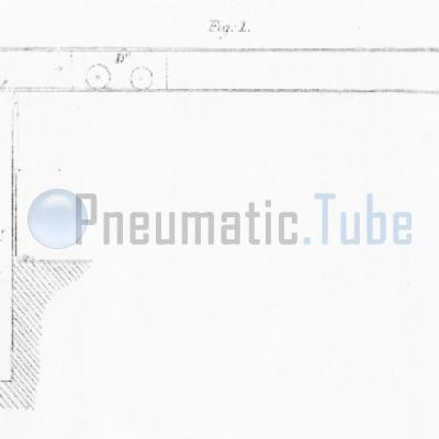
Figure 1 - The Pneumatic Despatch Tube, with valves, V V', at both ends.
Figure 2 - The Fan-wheel and stationary engine.
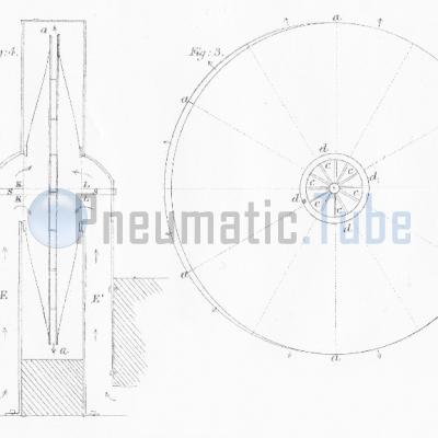
Figure 3 - The fan-wheel, showing its central orifice at c, c, c, and the bearingring d, d, d, which works against the in-draught pipe E.
Figure 4 - Section of fan-wheel in its inclosing case, showing its diminishing breadth from centre to periphery; the stationary engine, C, by which it is worked by the cranck, c, and the shaft, s s; at K K and L L, the air enters from the in-draught chambers, E E'; and is thrown off at the periphery, a, a, a.
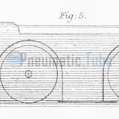
Figure 5 - One of the Euston pneumatic mail-carriages.
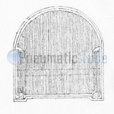
Figure 6 - Section of Euston pneumatic pipe, with rails and carriage within it.
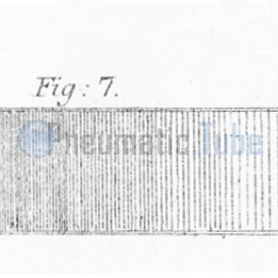
Figure 7 - End of Pneumatic Tube, showing by the increasing darkening of the tint the increasing pressure of air as the travelling carriage approaches the closed valve, V, and the effect of the piston, P, in allowing escape of air above the fixed pressure.
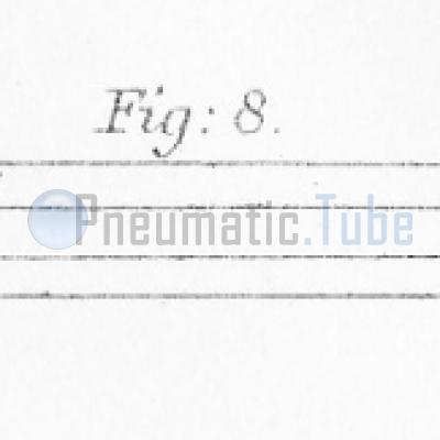
Figure 8 - The double exhausted Pneumatic Despatch Tube in use at the Central Telegraph Station in Moorgate-street; the exhaustion being continuous by a stationary engine at e; the parcels delivering themselves at the valves a or c.
The author, Samuel Joseph Mackie (21 January 1823 – 31 May 1902), was a British geologist, inventor, and editor. He was a founding member of the Geologists' Association and the Anthropological Society of London, and sole editor of The Geologist: a Popular Monthly Magazine of Geology, a precursor to the Geological Magazine.
This article is found in the first edition of the book Popular Science Review and was published in 1864 by Robert Hardwicke.
Because it is now far more than 70 years since this article was first published, and also more than 70 years ago that the author has past away, the article and drawings are believed to be in the public domain.
 Pneumatic Tube, Rohrpost, Buizenpost
The Pneumatic Despatch, by S. J. Mackie
Published: 20-12-2018
Last updated: 25-01-2019

Show related articles:
Pneumatic Tube Calendar
24 October 1864 (161 years ago)
Commissioning Pneumatic Tube Mail Hamburg, Germany
31 October 1874 (150 years ago)
Pneumatic Tube Mail railway in London, Great Britain out of business
1 October 1879 (146 years ago)
The Mix & Genest company was founded by the businessman Wilhelm Mix and the engineer Werner Genest in Berlin-Schöneberg
7 October 1897 (128 years ago)
Commissioning Pneumatic Tube Mail New York USA