Pneumatic Tube System - How it works
The driving force of a pneumatic tube system is pneumatics. Pneumatics can be traced back to Hero of Alexandria in the 1st century AD.
Imagine a hot summer day, relaxing on a terrace with a cold drink with a straw... By sucking at the end of the straw you create a vacuum in it. The liquid in the glass will be sucked into the straw by this vacuum. The liquid level in the straw is going down again, when you gently blow into the straw. This is the working principle of pneumatics.
Click on the images below to enlarge them!
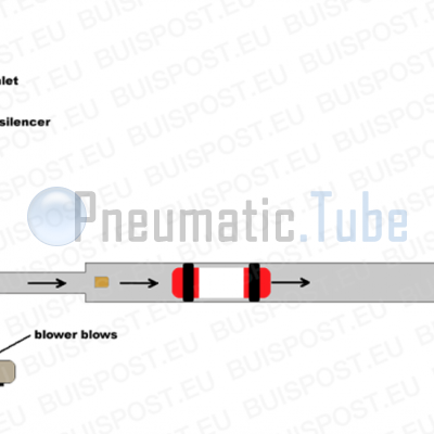
Explanation of picture #1
A pneumatic tube carrier has cuffs and will have a good fit in the transport tube. When we connect the end of the tube to a blower and we let the blower blow, a excess pressure is created in the tube. The pneumatic tube carrier will post pattern on the pressure and will move away from the blower.
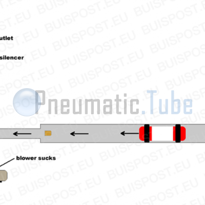
Explanation of picture #2
Letting the blower suck will create a vacuum in the tube, through which the carrier will move into the direction of the blower again. This way the carrier moves through the transport tube.
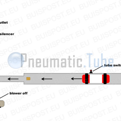
Explanation of picture #3
How does the central processing unit know when the carrier has arrived at its destination? Therefore we have the tube switch present. The tube switch detects the carrier in the tube and in this case will give a signal to the central processing unit to switch off the blower.
Perfect, the carrier can move back and forth, and the blower can be turned off. It almost looks like a real pneumatic tube system. But if the blower is switch off, the carrier will still have a significant speed, the carrier will not immediately come to a halt and will collide to the end of the tube. This isn't good for the technical condition of the carrier, let alone the content. To solve this problem we are using an air brake.
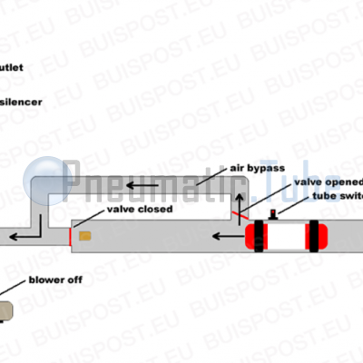
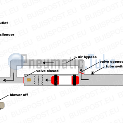
Explanation of picture #4 and #5
An air brake is build with two ducts and two air valves. If one valve is open, the other is automatically closed. The pressure of the blower will do this automatically, there is no need for an external control.
The valves are placed in such a way that when a carrier is sucked to the blower, the air will go through the bypass pipe.
The carrier will pass the tube switch, which shall switch off the blower. The carrier will be stopped by the air buffer in the tube. The rest of the air will flow through the bypass tube, and has no longer affect to the carrier.
By lengthening the bypass the inhibition of the carrier will be softer.
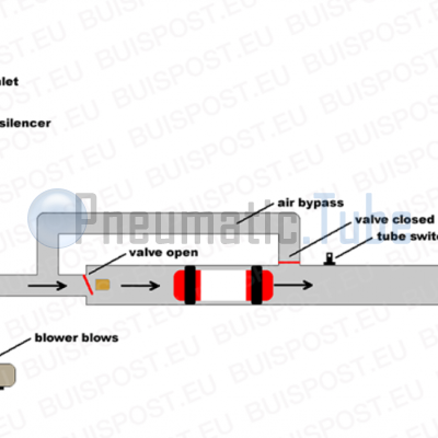
Explanation of picture #6
The blower is going to blow, and the position of the valves will change. The bypass valve is closed and the air will blow the carrier to the destination station.
At the station, the carrier will be detected also by a tube switch in a similar manner, and will be slowed down by the built-in air break.
Another component of a pneumatic tube system is the diverter. This is necessary to move the carrier from one track to another to continue its journey. This way you can connect several stations to a system. Again a tube switch detects where the carrier is located, before or after the diverter.
Normally there is only one carrier in a tube, but due to a technical fault it would be possible to have two in it. The carriers can never collide because they are both subject to the same driving force.
 Pneumatic Tube, Rohrpost, Buizenpost
Pneumatic Tube System - How it works
Published: 20-04-2013
Last updated: 19-04-2021

Show related articles:
Pneumatic Tube Calendar
24 October 1864 (160 years ago)
Commissioning Pneumatic Tube Mail Hamburg, Germany
31 October 1874 (150 years ago)
Pneumatic Tube Mail railway in London, Great Britain out of business
1 October 1879 (146 years ago)
The Mix & Genest company was founded by the businessman Wilhelm Mix and the engineer Werner Genest in Berlin-Schöneberg
7 October 1897 (128 years ago)
Commissioning Pneumatic Tube Mail New York USA