The Pneumatic Railway in the Grounds of the Crystal Palace
Article found in the Illustrated London News of Saturday 10 September 1864.
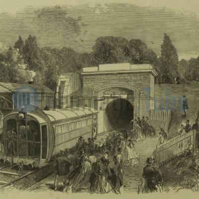
We give an Illustration of the Pneumatic Railway, invented by Mr. T. W. Rammell, C.E., a working model of which has, during the last two weeks, been exhibited in the grounds of the Crystal Palace. It extends from the Sydenham entrance to the armoury, near the Penge gate, a distance of nearly six hundred yards. A brickwork tunnel, about 10 ft. high by 9 ft. wide, and capable of admitting the largest carriages used on the Great Western Railway, has been laid with a single line of rails, fitted with opening and closing valves at each extremity, and supplied with all other apparatus for propelling passenger-trains on this principle, by a strong drought of air behind the train when it travels in one direction, and pumping away the air in front of it when it travels the other way. The motive power is supplied by this contrivance. At the departure-station a large fanwheel, with an iron disc, concave in surface and 22 ft. in diameter, is made to revolve, by the aid of a small stationary engine, at such speed as may be required, the pressure of the air increasing, of course, according to the rapidity of the revolutions, and thus generating the force necessary to send the heavy carriage up a steeper incline than is to be found upon any existing railway. The disc gyrates in an iron case resembling that of a huge paddlewheel; and from its broad periphery the particles of air stream off in strong currents. When driving the air into the upper end of the tunnel to propel the down-train fresh quantities rush to the surface of the disc to supply the partial vacuum thus created; and, on the other hand, when the disc is exhausting the air in the tunnel with the view of drawing back the up-train, the air rushes out in perfect hurricane from the escape valves of the disc case. When the down journey is to be performed the breaks are taken off the wheels, and the carriage moves by its own momentum into the mouth of the tube, passing in its course over deep air-well in the floor, covered with an iron grating. Up this opening a gust of wind is sent by the disc, when a valve, formed by a pair of iron doors, hung like lock-gates, immediately closes firmly over the entrance of the tunnel, confining the increasing atmospheric pressure between the valve and the rear of the carriage. The force being thus brought to bear upon the end of the train, the latter, shut up within the tube, glides smoothly along towards its destination, the revolving disc keeping up the motive power until it reaches the steep incline, whence its own momentum again suffices to carry it the rest of the distance. The return journey, on the contrary, is effected by the aid of the exhausting process. At a given signal a valve is opened, and the disc-wheel set to work in withdrawing the air from the tube. Near the upper end of the tube there is a large aperture, or side-vault, which forms the throat through which the air is exhaled, the iron doors at the upper terminus still being kept shut. In a second or two the train posted at the lower terminus, yielding to the exhausting process going on in its front, and urged by the ordinary pressure of the atmosphere from behind, moves off on its upward journey, and, rapidly ascending the incline, approaches the iron gates, which fly open to receive it, and it emerges at once into daylight. Instead of a train being used at Sydenham, there is one very long, roomy, and comfortable carriage, resembling an elongated omnibus, and capable of accommodating some thirty or thirty-five passengers. Passengers enter this carriage at each end, and the entrances are closed with sliding glass-doors. Fixed behind the carriage, there is a framework of the same form, and nearly the same dimensions, as the sectional area of the tunnel, and attached to the outer edge of this frame is fringe of bristles forming a thick brush. As the carriage moves along through the tunnel the brush comes into close contact with the arched brickwork, so as to prevent the escape of the air. With this elastic collar round it, the carriage forms a close-fitting piston, against which the propulsive force is directed. Although the curve in the tunnel is unusually sharp, being of eight chains radius, and the gradients are as high as one in fifteen (those of Holborn-hill being only one in eighteen), it is surprising that the motion is much steadier and pleasanter than ordinary railway traveling. The journey of 600 yards is performed either way in about fifty seconds, with an atmospheric pressure of only two ounces and half to the square inch; but a higher rate of speed, if desirable, can easily be obtained.
The author of the article and the artist of the drawing are unknown. Since they are published far more than 70 years ago, both are believed to be in the Public Domain.
Sources and more information
 Pneumatic Tube, Rohrpost, Buizenpost
The Pneumatic Railway in the Grounds of the Crystal Palace
Published: 26-01-2019
Last updated: 23-12-2019

Show related articles:
Pneumatic Tube Calendar
24 October 1864 (160 years ago)
Commissioning Pneumatic Tube Mail Hamburg, Germany
31 October 1874 (150 years ago)
Pneumatic Tube Mail railway in London, Great Britain out of business
1 October 1879 (146 years ago)
The Mix & Genest company was founded by the businessman Wilhelm Mix and the engineer Werner Genest in Berlin-Schöneberg
7 October 1897 (128 years ago)
Commissioning Pneumatic Tube Mail New York USA