Scientific American: Pneumatic Mail Tube System, New York City
Article found in the Scientific American - a weekly journal of practical information, art, science, mechanics, chemistry and manufactures - of December 11, 1897.
You can find the described pictures below the text.
The transmission of matter through closed tubes by means of a current of air flowing therein is not by any means a novel idea, although its successful application to commercial purposes is of recent date. For the earliest suggestion of pneumatic transmission we must go back to the seventeenth century and search among the records of that venerable institution, the Royal Society of London. Here we find that Denis Papin presented to the society in the year 1667 a paper entitled the "Double Pneumatic Pump." He exhausted the air from a long metal tube, in which was a traveling piston which drew after it a carriage attached to it by means of a cord. At the close of the eighteenth century a certain M. Van Estin propelled a hollow ball containing a package through a tube several hundred feet long by means of a blast of air ; the device, however, was regarded more as a toy than a useful invention. Of more practical value were the plans of Medhurst, a London engineer, who published pamphlets in 1810 and 1813 and again in 1833, when he proposed to connect a carriage running inside the tube with a passenger carriage running above it.
The distinction of being the first city to install a practical pneumatic tube system belongs to London, where in 1853 a 1 1/2 inch tube was laid between Founders' Court and the Stock Exchange, a distance of 330 yards. The carrier was drawn through the tube by creating a vacuum, a steam pump being used for the purpose. The roughness of the interior of the iron tubes gave much trouble, and when subsequent extensions of the system were made in 1858 and later, 2 1/4 inch lead tubes were used, the carriers being made of gutta percha with an outer lining of felt.
In 1865, Siemens & Halske, of Berlin, laid down in that city a system of pneumatic tubes for the transmission of telegraph messages. The wrought iron tubes, 2 1/2 inches in diameter, were in duplicate, one being used for transmitting and the other for receiving messages. They ran from the telegraph station to the Exchange, a distance of 5,670 feet. The tubes were looped together at the Exchange and a continuous flow of air was maintained by a compressor at one end and an exhauster at the other. The modified system now in use is worked by means of large storage tanks, containing either compressed or rarefied air, and it comprises 38 stations and more than 28 miles of tubing 2.55 inches in diameter.
The pneumatic tube system in Paris dates from the same year as that of Berlin. Here a novel feature was introduced in the method of compressing the air, for instead of using a steam engine it was compressed in tanks by displacement with water from the city mains. The tubes of the present system are 2.55 inches diameter, and the carriers are made up in trains of from 6 to 10, with a leather-covered piston at the rear, which fits the tubes snugly and drives them forward. The tubes are of wrought iron and the speed is 15 to 23 miles an hour.
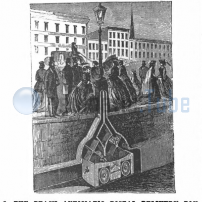
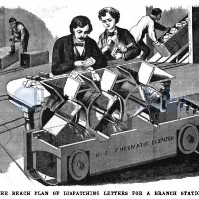
The father of the pneumatic tube system of railways in America was the late Alfred Ely Beach, who for half a century was one of the proprietors of the Scientific American. His experimental railway was first exhibited at the American Institute Fair held in New York City in 1867. A car capable of seating ten people ran upon a track laid down within a circular wooden tube, which was six feet in diameter and one hundred and seven feet long. The current of air was furnished by a 10 foot helix fan running at 300 revolutions per minute. He then constructed at his own expense an eight foot tunnel, which extended beneath Broadway from the corner of Warren Street to the south side of Murray Street, a distance of 300 feet. The car was propelled by a powerful rotary blower in the basement of an adjoining building, and the car was driven in alternate directions by reversing the valves of the blower. The tunnel is still in existence. Less known but equally meritorious was the system of pneumatic postal tubes designed by Mr. Beach at about the same period. We present two illustrations. Figs. 9 and 10, which were made many years ago under his own direct supervision and need but little description. The letters and packages were to be delivered to cars from revolving hoppers, whose revolution was effected by pins on the edges of the cars striking the vanes. Delivery was effected by tripping the hinged bottom of the car, this also being done by a striking pin. In 1870, also, he built an 8 inch iron tube a thousand feet long, whose interior was glazed to form a smooth surface. This led to a large receiving box, from which a second pipe led to an exhausting engine. A letter dropped into the pipe at any point was swept along by suction due to the exhaustion of the air from the box, and on reaching the box it fell to the bottom, from which it was easily removed.
The London system has grown steadily and now includes 42 stations and 34 miles of tubes. The latter are of cast iron and lined with lead. On the shorter lines the inside diameter is 2 3/16 inches, and on the longer lines 3 inches. The lines are laid out radially, air being compressed at one end and exhausted at the other. Similar systems are used in connection with the telegraph service in Liverpool, Manchester, Birmingham, Glasgow, Dublin and Newcastle. Mention should be made here of the underground pneumatic railways constructed in London, the first built in 1863, 1,800 feet in length and 2 feet 8 inches by 3 feet 8 inches in section ; the later tunnels, built in 1872, running from Euston Station to the general post office, a distance of 2 3/4 miles. The latter was in duplicate and D-shaped in section, measuring 4 1/2 feet wide by 4 feet high, the straight portion being of cast iron and the bends of brick. It was operated by a fan, which forced air into one tunnel and exhausted it from the other. The capacity of the line was about one ton per minute. It was not satisfactory and was ultimately abandoned.
The pneumatic tube has been in use in this country on a small scale for a quarter of a century for the transmission of cash in retail stores and for general telegraphic purposes. The Western Union Telegraph Company laid down four lines in 1876 from the main office in Broadway, New York — two to the branch office at 14 Broad Street, one to Pearl Street, and one to the Cotton Exchange. To these it has since added two miles of double line which run beneath Broadway to its uptown office.
The most notable event in the recent history of pneumatic transmission occurred in Philadelphia, when a system of 6 inch tubes was built between the main post office and the sub-post office on Chestnut Street, near Third Street, a distance of 3,000 feet. The reader will observe that in all the European systems none of the tubes are larger than 3 inches in diameter, so that in respect of size alone the Philadelphia plant marked a bold advance upon any existing system, the area of the tubes being increased more than four-fold, and the capacity of the carriers in proportion. The speed, moreover, was nearly doubled, and hence, with the improved mechanical appliances for transmitting and receiving, the capacity of each tube cannot be less than twenty times as great as that in the old country systems. The Philadelphia plant was opened in 1893 and has been in successful operation ever since.
In 1897 the Tubular Dispatch Company, of New York, was authorized to construct a system of postal delivery tubes between the general post office and certain sub-stations in New York City. It was decided to adopt the system already in successful operation in Philadelphia, and to this end the Batcheller Pneumatic Tube Company, of Philadelphia, drew up plans for a set of lines running from the general post office to the Produce Exchange, to the Forty-second Street depot, to One Hundred and Twenty-fifth Street, and across the Brooklyn Bridge to Brooklyn. The line to the Produce Exchange and return was built, and the opening took place on October 7 of this year. The Forty-second Street line is approaching completion, and it is expected that the others will be commenced at an early date.
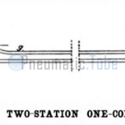
Encouraged by the success of the large tubes adopted on the Philadelphia line, the company determined to make the New York tubes two inches larger, or eight inches in diameter, and to maintain a regular working speed of 30 miles an hour under a headway of 12 1/2 seconds. The capacity of the tubes is thus increased to from 40 to 50 times that of the largest of the tubes in use on the European lines. The two-station branch already completed extends from the general post office to a sub-post office at the Produce Exchange, a distance of 3,750 feet. There are two parallel tubes 8 inches in diameter laid side by side at a distance of from 3 to 8 feet below the street surface. They are connected by a loop at the Exchange, one being used for outgoing and the other for returning mail. Power is furnished by a compressor, C, Fig. 8, at the main station, A, which delivers air at 7 pounds pressure to the square inch to the outgoing tube. The air flows with an increasing velocity and decreasing pressure (the result of its elasticity) to the sub-station, B, at the Produce Exchange, where its pressure is about 3 3/4 pounds to the inch. From the sub-station it returns by the second tube, as shown by the arrows, to the main station and passes into a receiving tank, E, at which point its pressure has fallen about to that of the atmosphere. The suction of the compressor is connected to this tank and the air is thus caused to circulate continuously through the circuit of tubes.
The straight tubes are made of cast iron, carefully bored and reamed to a smooth finish. The bends, none of which are less than 8 foot radius, are made of seamless brass tubing, 8 3/4 inches internal diameter. The carriers are made of a plate of sheet steel, 1/32 of an inch in thickness, which is rolled into a cylinder, riveted and soldered. The front cover is dished to receive a filling of felt, which is covered with thick leather and forms a buffer to cushion the shocks to which the carrier is liable. The shell is 7 inches diameter by 3 feet long and it is kept from direct contact with the tubes by two bearing rings, one near each end, made of a fibrous woven material. These act as packing and afford a satisfactory sliding contact with the tubes. Their life is limited to about 1,000 miles. The carrier is closed by a hinged cover at the rear, which is locked by three radial bolts. The latter are driven into three holes in the shell by means of a rotating latch operating a cam attached to the cover. The cam is placed eccentrically on the cover, and when the latch is in place locking the bolts it clears the edge of the carrier. As the throwing over of the latch in unlocking the bolts causes the former to project several inches beyond the cover and in contact with the tubes, it will be seen that the carrier cannot become unlocked while it is in transit.
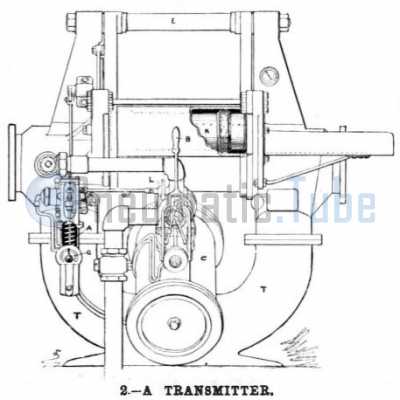
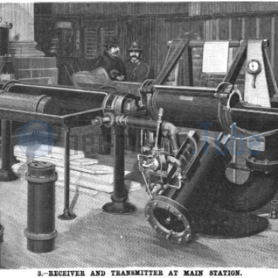
The carrier is introduced into the tube by means of transmitters, a, n. Figs. 3 and 8. The transmitter can best be described by supposing that a section long enough to inclose a carrier were sawed out of the main tube and hung from an overhead shaft, E, Fig. 3, parallel to the tube, in such a way that it could be swung away from the main tube to receive the carrier, and then swung back into line where the current of air could act upon the carrier and force it into the main tube. The ends of the movable section are planed and finished off perfectly smooth and square, so that no air can escape at the joints. When the movable section is swung out of line, two laterally projecting plates move across the ends of the main tube and prevent the escape of air, the current meanwhile traveling round the opening by means of a by-pass. The movements of the swinging section are controlled by an inclined pneumatic cylinder, C, whose valve is operated by a small hand lever, B. In the normal position, when the transmitter is not in use, the movable tube is drawn over opposite a loading tray, and the current passes through the U-shaped by-pass, T, which forms the legs of the carrier. When a carrier is to be sent it is placed on the tray and pushed into the swinging tube. The operator then pulls over the hand lever, B, thereby compressing a spring, which serves to push over the slide valve that operates the pneumatic cylinder. The slide valve may be prevented from moving, however, by a time look, A, which releases the former twelve and one-half seconds after a carrier has been dispatched. The time lock (which insures a proper headway between successive carriers in the tube) Is shown to the left of the pneumatic cylinder in Fig. 3 and in larger detail in Fig. 6. It consists of an oil cylinder, C, in which is a piston that is normally kept at the bottom of its stroke by a coiled spring. When the starting lever is pulled over, the time lock piston is drawn up against the spring, which at once begins to force the piston back, driving the oil around a by-pass valve, G, the time of its descent being regulated by the degree to which G is opened. At the bottom of its stroke an offset on the piston rod, J, pulls down a bell crank, N, which, by means of a connecting rod, O, withdraws the locking bolt, L, on the valve of the pneumatic cylinder and permits the latter to throw the transmitter into line.
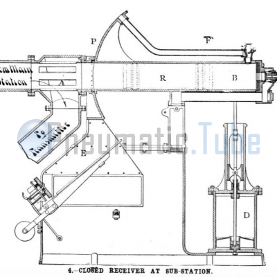
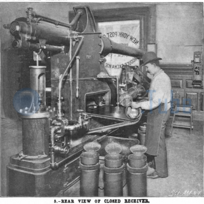
The carrier is impelled into the main tube and carried to the sub-station. As the air pressure at this point is 3 3/4 pounds to the square inch, it is impossible to open the tube for the purpose of removing the carriers. Moreover, as they arrive at a speed of 30 miles an hour, some provision has to be made for gradually checking their speed. These two results are obtained by means of the closed receiver. Fig. 4, which consists, like the transmitter already described, of a movable section of 8 inch tube. It is about double the length of a carrier, and is hung upon trunnions in much the same way as a telescope, the trunnions being placed midway of its length. In its normal position, as shown in Fig. 4, it forms a continuation of the tube by which the carrier arrives, and as the latter is impelled into the receiver, it compresses the air in front of it and is brought to rest without any harmful shock. Just in front of the receiver the main tube is provided with a number of slots, A, which by-pass the air into a tube which leads through the sub-station transmitter, n. Fig. 8, back to the main station. The compression of the air in the receiver by the entrance of the carrier opens a relief valve at the rear end, and so prevents the carrier from being thrown back into the main tube. The pneumatic cylinder, D, elevates the outer end of the receiver and tilts the latter on its trunnions, for the purpose of discharging the carrier on to the receiving table. This is accomplished automatically as follows : A small portion of the air compressed in the receiving chamber flows through a small pipe to a piston which controls the slide-valve of the tilting cylinder, B. The piston pushes down the piston slide-valve and admits air to cylinder, D, whose piston rises and by means of a connecting rod tilts the receiving chamber to an angle of 40 degrees. The carrier slides out an inclined and pivoted platform, E, which is kept in the inclined position by a counterweight. The weight of the carrier overbalancing the counterweight, the platform falls to a horizontal position and delivers the carrier onto a table in front of the operator, as shown in Fig. 5. An ingenious arrangement of bell cranks and rods connects the platform, E, with the slide valve of cylinder, D, so that the return of the former to the inclined position causes the cylinder to return the receiving chamber, B, to its normal horizontal position ready to receive the next carrier. Above the front end of the receiving chamber is a plate, P, carefully turned to the radius of the arc described by the chamber on its trunnions, which closes the end of the main tube when the chamber is in the tilted position. The interval from the arrival of a carrier to the return of the receiving chamber to the horizontal position is only 3 or 4 seconds.
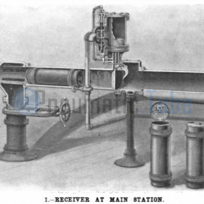
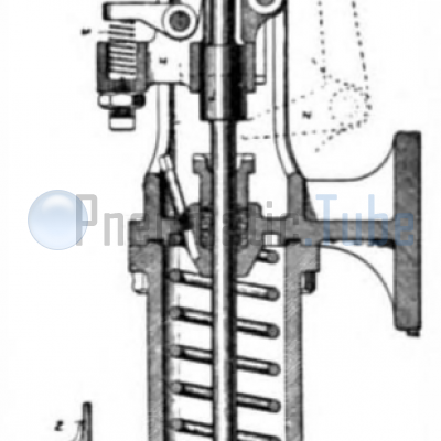
The transmitter, n, at the sub-station is similar to that at the main station, already described. The receiver at the main station, however, is entirely different from the one just described. Its construction is shown in detail in Fig. 1. The carrier arrives by the curved tube and passes into a receiving chamber, which is simply a section of tube closed by a vertical sluice gate. The current of air, now expanded to atmospheric pressure, passes from the main tube down a vertical pipe to the return tank, e, Fig. 8, in the basement. The distance from the slots through which the air passes to the tank, to the sluice gate, is about 4 feet, and the momentum of the carrier is absorbed in compressing the air ahead of the car as it enters this chamber. Part of this compressed air passes up through a small pipe, as indicated by arrows in Fig. 1, and enters a small cylinder, where it depresses a piston which is normally held at the top of its cylinder by a coiled spring. This cylinder is situated just above the piston slide-valve of a pneumatic cylinder, whose work is to raise and lower the sluice gate above mentioned. The depression of the small piston and the attached piston valve admits air at 7 pounds pressure below the piston of the pneumatic cylinder and raises the sluice gate, to which it is attached. The very slight pressure of the air behind the carrier is sufficient to force it out onto the receiving table. As the carrier passes out it strikes a small tripfinger, which moves the piston slide-valve back to normal position and shuts the gate. If the air pressure in the main tube is not sufficient to expel the carrier from the receiver, the vertical pipe that conducts the air current to the return tank is partially closed by means of the gate valve shown in Fig. 1.
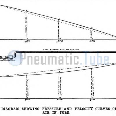
The diagram. Fig. 11, is inserted to show the principles of the system of pneumatic transmission above described. Air at say 10 pounds pressure is supposed to be constantly supplied at one end of an 8 inch tube one mile in length, the pressure falling until it leaves the other end at zero. The air being elastic it expands as it flows, and this expansion necessarily increases its velocity. The decrease in pressure and the increase in velocity are shown respectively by the curved lines in the upper and lower diagrams.
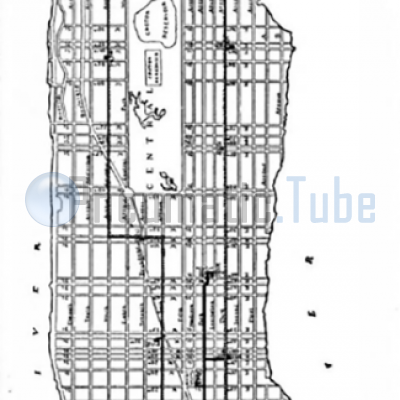
The accompanying map of a part of New York City shows the present and proposed lines of tubes contemplated by the Tubular Dispatch Company. The full black line indicates the lines already either completed or practically completed, and the dotted lines mark the proposed extensions.
For the drawings and data used in our description of this extremely interesting plant we are indebted to Mr. B. C. Batcheller, chief engineer of the Pneumatic Tube Company, who is the inventor of the salient features of the system.
The author of the article and the artist of the drawings are unknown. Since both are published far more than 70 years ago, they are believed to be in the Public Domain.
 Pneumatic Tube, Rohrpost, Buizenpost
Scientific American: Pneumatic Mail Tube System, New York City
Published: 18-04-2021
Last updated: 04-05-2021

Show related articles:
Pneumatic Tube Calendar
24 October 1864 (161 years ago)
Commissioning Pneumatic Tube Mail Hamburg, Germany
31 October 1874 (150 years ago)
Pneumatic Tube Mail railway in London, Great Britain out of business
1 October 1879 (146 years ago)
The Mix & Genest company was founded by the businessman Wilhelm Mix and the engineer Werner Genest in Berlin-Schöneberg
7 October 1897 (128 years ago)
Commissioning Pneumatic Tube Mail New York USA